Dom4uinLvNv
Really Experienced
- Joined
- Mar 14, 2011
- Posts
- 157
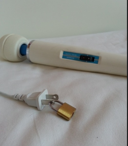
Best toy ever made..Next to a John Deer LoL And someone made a speed controller finally too.
http://www.amazon.com/Wand-Massager-Speed-Controller-Hitachi/dp/B000YA7Z22/ref=pd_rhf_ee_shvl2
Along with many attachments as well
http://www.amazon.com/Wand-Massager-Speed-Controller-Hitachi/dp/B000YA7Z22/ref=pd_rhf_ee_shvl2
Along with many attachments as well
")